« Puzzle: Sum of Uniformly Distributed Random Numbers | Main | Fourmilab: Network Architecture Drawing Online »
Tuesday, January 17, 2006
Fourmilab: Network Upgrade Complete
The seemingly endless network infrastructure upgrade at Fourmilab at last seems to be winding down.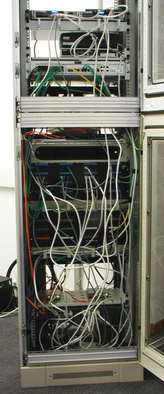 For the first time in months, it is actually possible to close the doors and install the back
panels on the top and bottom sections of the communications rack (although, as seen in
this picture, I haven't yet actually taken that momentous step). The rack is now 100% free
of “3Con” products. At the top, mounted side by a side in a 1U shell, are
the two Nokia IP265 FreeBSD-based firewalls which were
put into production last
December 8th. Sitting atop them is a
Netgear GS105
Gigabit Ethernet switch for the “external” network; this is the 193.8.230.0/24 address block assigned to Fourmilab by
RIPE.
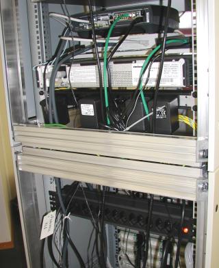
The only equipment connected directly to this switch are the external interfaces of the
primary and backup firewalls, and the Ethernet port of the Cisco 1720 router which terminates
the Internet connection on this end. The router is the dark box immediately below the cable
guides under the firewalls; it sits atop the Siemens 2 Mbit/sec leased line modem to which it connects. The router also has the ability to establish a 64 Kbit/sec dial-up ISDN connection in the event the leased line fails; given the load on the site, it is difficult to remotely distinguish a fail-over to this backup from a complete outage.
Below the tray which supports the modem and router is the Alcatel OmniPCX Linux-based PBX which provides ISDN wired and DECT wireless telephone service. The PBX has an Ethernet interface, and is managed from
a PC on the local network and, yes, it is behind the firewall and accepts no packets from the outside!
In the bottom half of the rack, the fibre optic patch panel is at the very top; four 65 µm multimode fibres run between the buildings and terminate here and in a small rack in the basement of the house. (Yes, singlemode 9 µm is cooler, but nobody was installing that when these fibres were pulled in 1994. Gigabit Ethernet [1000BASE-SX] works just fine
over 65 µm fibre for a run this short: less than 100 metres.)
Beneath the fibre patch panel is a cable feed-through which is currently unused,
and then the main RJ-45 patch panel (with jacks labeled in blue) where all the
wall outlets in the building terminate. Below that is another cable guide and
then the telephone patch panel
where the external ISDN lines terminate; these are patched to jacks
on the PBX in the top section of the rack. Most of the jacks in this panel are unused
because they used to be connected to the prior Alcatel 4220 PBX, which was mounted
on the wall behind the rack; with its replacement by the rack-mounted OmniPCX, they
have lapsed into desuetude. Below the telephone panel is another cable guide and a 1U patch panel where the 10 lines in the telephone cable between the buildings terminate, then
a large open space which used to be filled with the now-removed 3Con
“hang-o-matic” firewalls and switch.
A tray below the gap supports two Allied Telesyn fibre optic media converters, which interface
the fibre lines between the buildings to the Ethernet network. The one on the
right is the main AT-MC1004SC Gigabit Ethernet converter which bridges
the local network, and at left is an AT-MC101XL 100 MB/s Ethernet converter which acts
as a backup for the Gigabit converter and can be used to extend other networks
(for example, the DMZ on which the servers live, or “toy” networks
assembled for testing) between the buildings.
For the first time in months, it is actually possible to close the doors and install the back
panels on the top and bottom sections of the communications rack (although, as seen in
this picture, I haven't yet actually taken that momentous step). The rack is now 100% free
of “3Con” products. At the top, mounted side by a side in a 1U shell, are
the two Nokia IP265 FreeBSD-based firewalls which were
put into production last
December 8th. Sitting atop them is a
Netgear GS105
Gigabit Ethernet switch for the “external” network; this is the 193.8.230.0/24 address block assigned to Fourmilab by
RIPE.
The only equipment connected directly to this switch are the external interfaces of the
primary and backup firewalls, and the Ethernet port of the Cisco 1720 router which terminates
the Internet connection on this end. The router is the dark box immediately below the cable
guides under the firewalls; it sits atop the Siemens 2 Mbit/sec leased line modem to which it connects. The router also has the ability to establish a 64 Kbit/sec dial-up ISDN connection in the event the leased line fails; given the load on the site, it is difficult to remotely distinguish a fail-over to this backup from a complete outage.
Below the tray which supports the modem and router is the Alcatel OmniPCX Linux-based PBX which provides ISDN wired and DECT wireless telephone service. The PBX has an Ethernet interface, and is managed from
a PC on the local network and, yes, it is behind the firewall and accepts no packets from the outside!
In the bottom half of the rack, the fibre optic patch panel is at the very top; four 65 µm multimode fibres run between the buildings and terminate here and in a small rack in the basement of the house. (Yes, singlemode 9 µm is cooler, but nobody was installing that when these fibres were pulled in 1994. Gigabit Ethernet [1000BASE-SX] works just fine
over 65 µm fibre for a run this short: less than 100 metres.)
Beneath the fibre patch panel is a cable feed-through which is currently unused,
and then the main RJ-45 patch panel (with jacks labeled in blue) where all the
wall outlets in the building terminate. Below that is another cable guide and
then the telephone patch panel
where the external ISDN lines terminate; these are patched to jacks
on the PBX in the top section of the rack. Most of the jacks in this panel are unused
because they used to be connected to the prior Alcatel 4220 PBX, which was mounted
on the wall behind the rack; with its replacement by the rack-mounted OmniPCX, they
have lapsed into desuetude. Below the telephone panel is another cable guide and a 1U patch panel where the 10 lines in the telephone cable between the buildings terminate, then
a large open space which used to be filled with the now-removed 3Con
“hang-o-matic” firewalls and switch.
A tray below the gap supports two Allied Telesyn fibre optic media converters, which interface
the fibre lines between the buildings to the Ethernet network. The one on the
right is the main AT-MC1004SC Gigabit Ethernet converter which bridges
the local network, and at left is an AT-MC101XL 100 MB/s Ethernet converter which acts
as a backup for the Gigabit converter and can be used to extend other networks
(for example, the DMZ on which the servers live, or “toy” networks
assembled for testing) between the buildings.
 Below the tray is the Cisco Catalyst 2970 Gigabit Ethernet switch for the internal
network (LAN). All 24 ports on this switch are 10/100/Gigabit automatic switching,
and the switch can be managed either through a console port with Cisco's IOS command
line facility or from a Web interface using a built-in HTTP server. The physically
separate DMZ network on which the public servers reside is connected by redundant
Gigabit Ethernet switches mounted in the
server
rack in the Hall of the Servers downstairs; these switches are patched
directly to the DMZ interfaces of the two firewalls. (Isolating the servers on a DMZ
network means that even if one or more of them should be compromised, they
cannot be used as a “beachhead” to attack machines on the local
network.)
Sitting on the floor
at the bottom of the rack are the adaptor boxes for the four Swisscom ISDN lines connected to
the telephone patch panel; they're intended to be wall mounted, but there isn't
a conveniently located wall, so that's where the installer dumped them
a decade ago and that's where they've been ever since. There used to be a
big rack-mount UPS at the very bottom of the rack, but after its
batteries
melted down a little over a year ago, I replaced it with the floor mount UPS
you can see at the very bottom of the above right photo, having learnt to never again
install a UPS in a rack.
A single cable from the APC SUA1500I UPS powers a 15 outlet strip mounted on the back rail of the rack (see the image at the left) into which is plugged a 6 outlet right-angle power strip (visible at the bottom of the top section of the rack) for “wall wart“ power cubes, which would otherwise devour all
the free outlets on the main power strip.
Below the tray is the Cisco Catalyst 2970 Gigabit Ethernet switch for the internal
network (LAN). All 24 ports on this switch are 10/100/Gigabit automatic switching,
and the switch can be managed either through a console port with Cisco's IOS command
line facility or from a Web interface using a built-in HTTP server. The physically
separate DMZ network on which the public servers reside is connected by redundant
Gigabit Ethernet switches mounted in the
server
rack in the Hall of the Servers downstairs; these switches are patched
directly to the DMZ interfaces of the two firewalls. (Isolating the servers on a DMZ
network means that even if one or more of them should be compromised, they
cannot be used as a “beachhead” to attack machines on the local
network.)
Sitting on the floor
at the bottom of the rack are the adaptor boxes for the four Swisscom ISDN lines connected to
the telephone patch panel; they're intended to be wall mounted, but there isn't
a conveniently located wall, so that's where the installer dumped them
a decade ago and that's where they've been ever since. There used to be a
big rack-mount UPS at the very bottom of the rack, but after its
batteries
melted down a little over a year ago, I replaced it with the floor mount UPS
you can see at the very bottom of the above right photo, having learnt to never again
install a UPS in a rack.
A single cable from the APC SUA1500I UPS powers a 15 outlet strip mounted on the back rail of the rack (see the image at the left) into which is plugged a 6 outlet right-angle power strip (visible at the bottom of the top section of the rack) for “wall wart“ power cubes, which would otherwise devour all
the free outlets on the main power strip.
Posted at January 17, 2006 15:51