|
|
By the end of 1986, AutoCAD's user interface was looking pretty antiquated. In October 1986 we'd shipped AutoSketch which had, for the time, a rather nice interface including pull-down menus and dialogue boxes. Many people felt that outfitting AutoCAD with such ease-of-use features would be a massive job requiring major modifications all over the program, further complicated by the need to maintain compatibility with existing menus, scripts, and other application components.
I wasn't sure it was all that tough. The moment the company shut down for the Annual Week of Rest between Christmas and New Year, I launched into a fury of round-the-clock programming, integrating the user interface manager from AutoSketch into AutoCAD, then extending AutoCAD's menu system to permit user-customisable pull-down menus and adding dialogue boxes to control many aspects of the program. By the time the company re-opened on January 4, 1987 it was all working as described in the following document which I stuffed into all the programmers' boxes so they'd find it when they got into the office that Monday. This was the first high-profile “Holiday Hack” and, along with the Portable Data Base project (see page
), which I did the next month, formed the centrepiece of AutoCAD Release 9.
A new user interface can be added to AutoCAD in incremental steps without sacrificing open architecture. Installation of this capability may spark the next large growth in sales.
by John Walker
January 1st, 1987
The evolution of AutoCAD's user interface has, to a large extent, recapitulated the evolution of user interfaces within the computer industry since the advent of timesharing.
The first programs designed for timeshared computers were command driven. These programs required the user to learn and become facile with a fairly large set of commands expressed as words or abbreviations and entered on a keyboard. As time passed, programs came to provide assistance to the user in the form of on-line help, command completion, and user-definable macros.
As on-line systems were adopted for commercial applications in the 1970's, menu driven user interfaces became increasingly popular. In a menu driven system, the user's major act of volition is choosing from a set of alternatives presented by the computer. Such systems can lead the user through a maze of functions with minimal confusion. In such systems, however, it is clear that the computer is in charge and the user is at best a guide and at worst a peripheral.
Research on how untrained users, particularly children, perceive computers led to the development in the early 1970's of the first event driven user interface: the Smalltalk system developed by Alan Kay at Xerox PARC. Event driven systems superficially resemble menu based systems, but differ in that the user is in control, generating requests of the system which are performed regardless of its state. Event driven systems tend to use a flat command space model and are largely devoid of modes.
AutoCAD began as a completely command driven program, and was consequently an exemplar of the first class of timesharing applications. Immediately prior to COMDEX 1982, a screen menu was added to AutoCAD, complementing the preexisting rudimentary tablet menu facility. Commands generated by menu selections were allowed to pause for user input, allowing the development of simple menu macros. In 1983 and 1984 the AutoCAD menu facility underwent further development, culminating in the release of AutoCAD 2.0 in October of 1984. This package incorporated a true menu programming language, allowing replacement of menus and submenus, and supported four separate tablet menu areas, a button menu, and the screen menu simultaneously. This package, along with a hierarchically structured menu released in conjunction with it, advanced AutoCAD into the second generation of user interface.
Unlike many other programs which made this jump, AutoCAD added menu-driven capability on top of the existing command-driven architecture, preserving the preexisting interface for users who preferred it. Since AutoCAD is an open architecture program and has always encouraged its users to extend it, this was particularly important. An open architecture program such as AutoCAD is founded on the concept of its command language being a programming language. Only a command-driven language is well suited to interpretation as a programming language and the retention of AutoCAD's original command language, and its extension, first through menu macros and later with AutoLISP, contributed to the acceptance of AutoCAD as the standard for desktop computer aided design.
Many observers of the development of software believe that programs cannot evolve from one generation of user interface to another without being rewritten. Indeed, many programs have been rewritten concurrently with being fitted with a contemporary interface. In addition, the goal of open architecture as exemplified by an extensible command set, programmability, and mutability of the interaction with the user, is often viewed as detrimental to the goal of a consistent event driven user interface. Most event driven programs (the majority of which haven been developed for the Smalltalk system and its derivatives such as the Xerox Star and the Apple Lisa and Macintosh) have been closed architecture systems, providing little or no ability for the user to tailor the system.
Those who have extensively used command-, menu-, and event-driven systems commonly remark that these systems form a continuum. The command based system is the hardest for the new user to learn, but the most productive in the hands of the experienced “power user”. The event driven system, though easily mastered by the beginner, delivers little more productivity to the user who uses it constantly. An open architecture package must also consider the consequences of the adoption of a new user interface on its extensibility and the base of applications which have been built upon it. Since the history of computing has demonstrated that open architecture, extensible systems predictably supplant closed architecture, proprietary systems, any modification of the user interface of a successful, established package must be carried out in an upward compatible, responsible fashion.
This article describes a set of modifications to AutoCAD which, taken as a whole, permit AutoCAD to present the user with a third generation event driven user interface. These modifications, while numerous, are individually minor. They build on AutoCAD's open architecture, making it the first true open architecture event driven program. The individual features described below work together in a tightly coupled fashion to deliver a far more responsive, intuitive, and transparent model of interaction with the user. They cannot be adequately evaluated by reading feature descriptions or by trying them in isolation. I recommend you see a demonstration of these new capabilities before attempting to understand the details of their implementation.
Some of these new capabilities require functionality not previously provided by AutoCAD display drivers, in particular the ability to save, restore, and clear rectangles on the screen, and to write text on the screen in any character cell position with normal, reverse, or disabled attributes. The display driver interface was extended to provide these additional functions in such a way that if an existing driver is not or cannot be upgraded, the new features will automatically be disabled, leaving existing AutoCAD functions unchanged. Several of the new features do not depend on the display driver extensions, and are present in all AutoCAD configurations.
A menu bar and pull-down menus are provided via extensions to the existing menu facility. Ten new menu sections are defined, named POP1 through POP10. If the display driver is capable of supporting the new user interface, and the status line is configured, AutoCAD scans the POP menu areas and assembles a menu bar consisting of the first lines of each of the pop-up menu sections. If no ***POPn sections are defined, or the display driver lacks the extended functions, or the status line is deconfigured, the menu bar and pop-up menu facility will be automatically disabled. Any POPn menu sections present will be ignored.
The menu bar is displayed by moving the pointer above the top of the graphics screen (exactly as the standard screen menu is activated by moving to the right of the graphics area). When the pointer moves off the top of the screen, the status line and first line of the standard screen menu are replaced by the menu bar. If the cursor is lowered back into the graphics area, the status line reappears. The menu bar may be accessed only with a physical pointing device—the arrow keys may not be used to display the menu bar.
When the cursor is moved over an item in the menu bar, it highlights by flipping to reverse video. If the pick button is pressed while a menu bar title is highlighted, a menu will appear on the screen below the title. Moving the cursor within a menu highlights items within it, and picking a highlighted menu item executes the commands associated with it. A pulled down menu remains down until either an item from it is picked, another menu is pulled down by picking it from the menu bar, the menu is removed by picking an unused section of the menu bar, or a point is selected by picking a point on the graphics screen, or a character is typed on the keyboard.
Pull down menus behave exactly as any other menu sections, and menu macros may be defined exactly as one would for the standard screen or tablet menus. Menu labels, which are limited to 8 characters for most display devices, may be of any length within POP menu sections.
Menu and submenu swapping via “$” commands may be used with pop-up menus. The pop-up menu areas are named P1 through P10 for menu swapping purposes. The following illustrates a menu swapping sequence.
***POP5
**P5A
[Submarine]
Ready
Aim
[Fire]$P5=P5B
Ready
[Steady]*^Credo
Go
[--]
[Test Sonar]^Cgrid on
[Raise periscope]^Csnap on
[Lower periscope]^Csnap off
[--]
[Crash dive]^Cquit y
**P5B 4
[Fire 2]$P5=P5C
**P5C
UpScope
[Torpedos]$P5=P5D
Running
   .
   .
   .
[Ping]$P5=P5A
**P5D 2
[~Empty]$P5=P5E
**P5E 2
[Torpedos]$P5=P5D
Since the title which appears in the menu bar is simply the first line of the menu, the title may be changed by replacing that line of the menu with a $Pn= command. If the first line of the menu section is blank, no entry for it will appear in the menu bar. This allows you to turn whole menus on and off. This may not be a good idea in user interface design, but if you want to do it, you can.
If a menu item begins with a tilde (“~”), it will be displayed “greyed out”, indicating that it is not a valid selection. The action taken when such a menu item is selected is up to the creator of the menu. If the item is a label with no commands, selecting it will have no effect. However, if you wish to have a greyed out menu item execute commands, you need only supply them. A menu item with a label of two minus signs is expanded to a separator line which fills the entire width of the menu. These items usually have no effect when picked, but again, if you supply commands to execute, AutoCAD will comply.
To allow more convenient object selection, three new commands were added to AutoCAD's “Select objects:” mechanism. These commands may be used to adapt object selection to the form best suited to a given command. The design for these new facilities draws heavily on the object selection rules in AutoSketch.
If you type BOX to the “Select objects:” prompt, AutoCAD will ask you to specify a window by two corners, as for the WINDOW and CROSSING commands. If the first point entered is to the left of the second point, BOX is equivalent to WINDOW; if the second point is to the left of the first, BOX is equivalent to CROSSING. Using BOX in a menu allows the user to choose between WINDOW and CROSSING modes simply by how the box is drawn; no keyboard entry or further menu selection is required. The BOX command must be spelled out in full; no abbreviation is defined for it.
Entering AUTO (abbreviation AU) to the “Select objects:” prompt chooses automatic selection. A point is requested as for single object selection. If the specified point chooses an object, that single object is the result of the automatic selection. If no object is chosen by this pick, it will form the first corner of a BOX selection as described above. Using AUTO in a menu permits the user to choose by pointing, window, or crossing simply by the way the pick is made.
The specification SINGLE (abbreviation SI) places object selection in single selection mode. This disables the normal dialogue conducted by object selection, and causes it instead to return the first object or set of objects successfully selected by a subsequent command. The “Select objects:” prompt will continue to be issued until a selection is made, but that selection (whether a single object or multiple objects chosen by a window) will be reported without pausing for further interaction. For example, consider the following menu item:
[Erase]^Cerase single auto
When picked, this item terminates the current command and activates the ERASE command. The selection of objects to erase is done in SINGLE mode with the AUTO selection command. In operation, the user picks this command and either points to the single object to be erased, or points to a blank area and pulls a window (crossing to the left, enclosing to the right), around the objects to be erased. This is identical to the AutoSketch ERASE command, except that it does not repeat. SINGLE selection mode leads to more dynamic interaction with the user. A complex selection may be useful at infrequent intervals, but the selection dialogue was primarily a means of confirming the object of editing commands before they performed frequently irrevocable actions. Now that a general UNDO facility is available, this is much less important.
Once the user has selected a command, he is likely to use it several times before moving on to another. This is an outgrowth of how people use tools; you pick up a tool, do several things with it, then pick up another tool and so on. “If all you have is a hammer, everything looks like a nail.” AutoCAD's normal interaction model forces the user to pick up the hammer before driving each nail. The automatic command repetition triggered by null input was implemented as a response to this problem, but it does not permit command options to be specified. This can lead to the undesirable situation (oft complained about) where the user chooses one of the variants of arc input from the screen menu and draws one arc, then repeats the command by hitting the space bar and is surprised to be back in the “three points” form of the ARC command.
Many systems are designed so that most of the frequently used commands are modal. That is, they repeat automatically until another command is chosen. AutoCAD was not designed on this model, but with the provision of transparent commands for most viewing and mode setting functions, it may be easily simulated.
An extension to the menu macro language has been made as follows. If the first character of a menu command string is an asterisk, and that command string is picked as the response to the “Command:” prompt, the menu string is saved. Subsequent “Command:” prompts will be answered by that menu string until it is terminated by the entry of Control C from either the keyboard or from another menu item. It can be seen that if all major commands are chosen from menus, begin with Control C, and use the repetition option, modal operation is achieved. The following essentially emulates part of the AutoSketch Edit menu.
***POP2
[Edit]
[Move]*^Cmove single auto
[Copy]*^Ccopy single auto
[Erase]*^Cerase single auto
[Stretch]*^Cstretch single c
[Rotate]*^Crotate single auto
[Scale]*^Cscale single auto
While menu item repetition provides repeated execution of commands chosen from menus, the experienced user cannot repeat commands entered from the keyboard other than by improvising an AutoLISP macro on the fly. To provide this capability, a new MULTIPLE command is provided. If the MULTIPLE command is entered at the main “Command:” prompt, the next command entered is saved. When the “Command:” prompt reappears, that command will be automatically repeated unless a Control C was entered since the multiple command was activated. If a user wants to draw a bunch of circles, he may just say MULTIPLE CIRCLE and AutoCAD will repeat the CIRCLE command until a Control C stops it.
The MULTIPLE command does not issue a prompt, so the user is encouraged it view it as an adjective that modifies the next command. A console break will stop the iteration of a repeating command, so if you use MULTIPLE with a command that does not accept input, you can still stop it.
When a command is repeated by the MULTIPLE mechanism, the “repeat flag” which is set by repetition caused by a null input is not set. This was thought to be the most intuitive choice, as so few commands currently behave differently the user may not be aware of them and confuse their action with a bug in the MULTIPLE mechanism. Since the MULTIPLE command repeats only the command itself, parameters must be respecified on each subsequent execution.
Ever since the development of external commands via the .PGP file and user-defined commands in AutoLISP, users have repeatedly asked to be able to redefine built-in AutoCAD commands. Our concern in allowing this was that users would inadvertently render menus or AutoLISP programs unusable by redefining a command used somewhere in their guts. The facility implemented permits redefinition while guarding against the horrors it might lead to.
To delete the built-in AutoCAD definition of a command, use the UNDEFINE command. The command you name must be a known AutoCAD command, but may have been previously UNDEFINEd. To restore the built-in definition of a command, use the REDEFINE command, specifying the command to be restored.
Even if a command has been UNDEFINEd, it can always be activated by specifying its “true name”, which is simply the command name prefixed by a period. The following sample dialogue illustrates these commands:
Command: (defun C:LINE ()
1> (princ
2> "Shouldn't you be using Polyline?\n")
1> (command ".line"))
C:LINE
Command: line
From point:  *Cancel*
Command: undefine
Command name: line
Command: line
Shouldn't you be using Polyline?
.line From point: nil
From point:  *Cancel*
Command: redefine
Command name: line
Command: line
From point:
Menus, scripts, and AutoLISP programs which are expected to be run in environments in which redefinition is used should protect themselves by using the “.” forms of all commands. The UNDEFINE command operates only on main AutoCAD commands: those chosen from the “Command:” prompt. Subcommands, such as those used in the LAYER and PEDIT commands, and the dimensioning subcommands may not be UNDEFINEd.
A dialogue handler was installed in AutoCAD and used to implement several new commands which set AutoCAD modes via dialogue boxes. The dialogue handler is an extension of the one used in AutoSketch and AutoShade, and will be familiar in both appearance and operation to those who have encountered it before.
Since the dialogue handler requires the new display driver services, the commands which use it are only available on systems with a display driver which provides the new functions. Commands which use dialogues are flagged in the command table with a special prefix. Attempting to use one on a non-capable display will result in the message “** Command not allowed with this display configuration. **” and the command will be ignored. It is important that any new facility added to AutoCAD via a dialogue also be provided in the command language (or its equivalent, such as a system variable settable with SETVAR). This is essential for two reasons. First, users who lack a display which can show dialogues would be locked out from the new feature. Second, dialogues are only for direct on-line interaction with a user: AutoCAD facilities must also be made available from menu macros and AutoLISP, both of which must go through the command language interface. These constraints should in no way cause us to hesitate in freely using dialogues in AutoCAD: by presenting information to the user in a two dimensional form and by showing directly the interaction between features, they can improve the ease of use of the complex facilities that abound in AutoCAD by at least an order of magnitude.
Dialogue-oriented commands simply pop up the dialogue, talk to the user, and exit. They should not perform any conventional (text scrolling line) user input or output. Since dialogue commands will typically be activated from menu items, they may be given obscure names unlikely to conflict with anything. I've adopted the convention that all dialogue command names begin with DD (for Dynamic Dialogue). Dialogue commands should be transparent wherever possible. All dialogue commands are presently ADE-3.
When a dialogue appears, the cursor changes from whatever it was to an arrow. Every dialogue has an OK button and most have a Cancel button as well. Until the dialogue is dismissed by picking one of those two buttons, AutoCAD responds only to pointer motion, pointer picks, and the keyboard. The screen menu (including the menu bar), and all of the other menu areas will not respond, nor may the flip screen or other mode toggle keys be used. The arrow keys may be used to make dialogue box selections, but it's hardly practical to work that way.
The act of popping up a dialogue, making selections, and placing them into effect by picking the OK button is one command from the standpoint of the UNDO mechanism. As with a transparent SETVAR, mode changes made within a command will be UNDOne if the enclosing command is reversed.
Most dialogues contain one or more buttons. Each button controls a value. Picking the button affects the value in a way that depends on the type of the button.
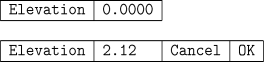
An input button specifies a value such as the snap spacing or the current drawing colour number. Picking an input button opens it and allows you to type values into it. Whilst open, an input button shows its own OK and Cancel subbuttons which may be used to accept or discard the value typed into the button. If you position the cursor over an input button so that it is highlighted, you may start typing into it without picking it. If an invalid value is entered, the OK button will have no effect; you should backspace, correct the value, and try again. Pressing the RETURN key is equivalent to picking the OK button, and pressing ESC is equivalent to picking the Cancel button. Values in input buttons are displayed and entered according to the settings of the UNITS command.
A requestor button looks like an input button, but when it is picked, the value area expands into an entire dialogue which is used to select the value for the button. When that dialogue is completed, the chosen value appears in the value area of the requestor button.
![]()
A toggle button controls a Boolean mode, such as whether the grid is shown on the screen. The value in a toggle button is shown as On or Off, and picking it flips it to the other value.

A check button is usually used to control selections from a set of alternatives, such as which isometric plane is to be used, or which layers are visible. A check button is a small rectangle which is either blank or shows a check mark (“✓”). If a family of check buttons control mutually exclusive modes, such as the isometric plane, checking one turns the previously checked button off. If the controlled modes are independent, such as layer visibility, the buttons will be independent of each other.
![]()
An action button does not control a value, but rather causes something to happen when picked. The OK and Cancel buttons are the most commonly encountered action buttons. Other action buttons perform such functions as scrolling a list of layer names up and down.
Errors within dialogues may result in the appearance of an alert. An alert is a small dialogue containing only a message and an OK button. After you read the message, get rid of the alert by picking the OK button.
The DDRMODES command pops up a dialogue which controls on-screen drawing aids. It subsumes all of the functions of the SNAP, GRID, AXIS, ORTHO, and ISOPLANE commands, and in addition provides direct control over BLIPMODE. The command is transparent.
The DDEMODES command displays a dialogue that sets the modes assigned to new entities. The functions of the COLOR, LINETYPE SET, LAYER SET, and ELEV commands are provided by this dialogue. The elevation and thickness are set by input buttons, and the colour, line type, and layer buttons activate dialogues used to choose the values from those known to AutoCAD. The DDEMODES command is transparent, but the values it sets may not take effect until the start of the next AutoCAD command. The only line types shown by the DDEMODES dialogue are those previously loaded in the drawing.
|
|