Most large format photographers quickly become familiar with mounting and removing lenses from lensboards of their cameras. Usually all that's involved in removing the rear element of the lens and the retaining ring, securing the front element to the lensboard with the retaining ring using a spanner wrench, then reinstalling the rear element. This procedure suffices for lenses with focal lengths in the moderate wide to long range, but extreme wide angle lenses present their own unique problems.
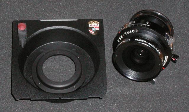
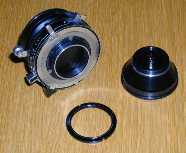
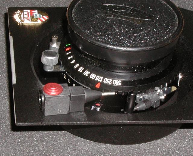
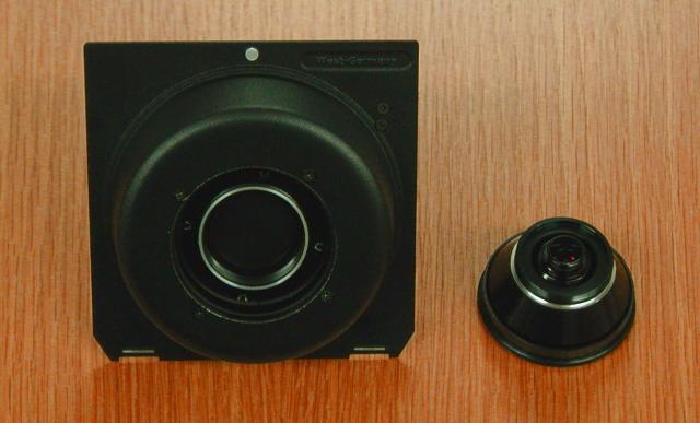
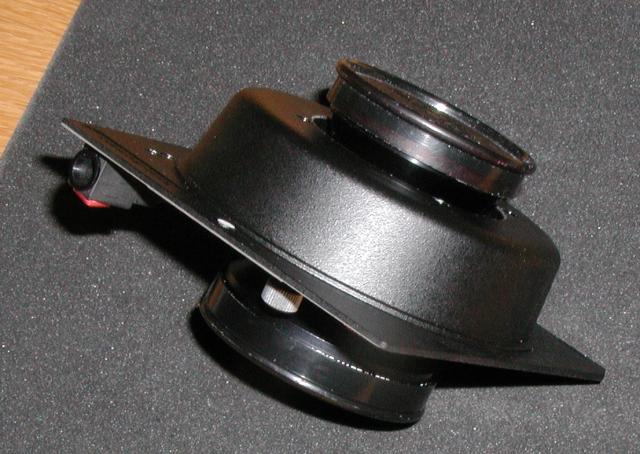
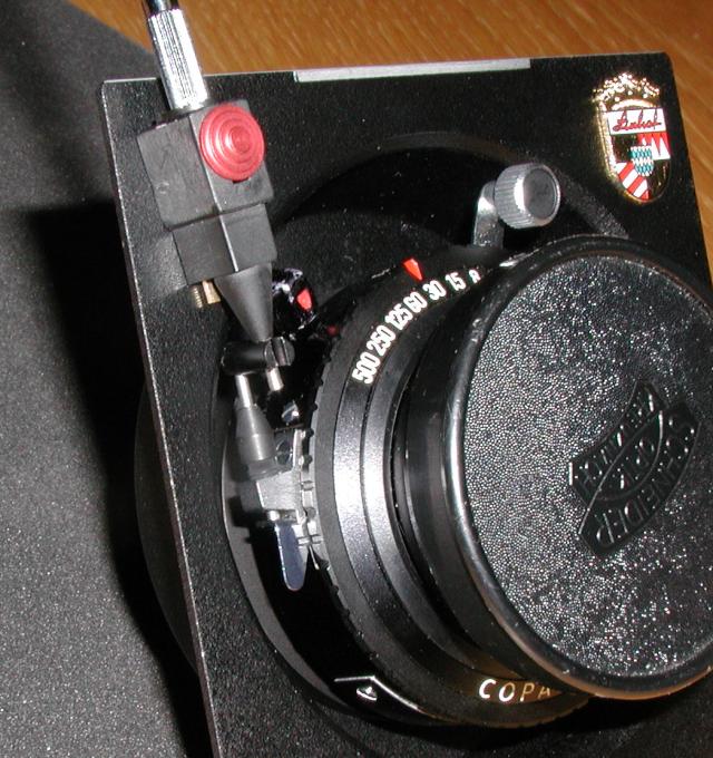
The bellows on most view cameras, even “bag bellows” intended to permit shifts and tilts with wide angle lenses, have a minimum extension due simply to the material from with they are constructed and their attachment to the standards. Extreme wide angle lenses, such as the Schneider Super Angulon 47mm and 58mm, often require, to focus at infinity, a lens to focal plane distance less than that achievable at minimum bellows extension. The work-around for this problem is to use a recessed lensboard, which displaces the lens into the camera body to a sufficient extent that it can be focused at infinity without exceeding the minimum extension of the bellows. In this document we'll consider the specific case of cameras which use Linhof Technika lensboards, on which we wish to mount a Schneider Super Angulon (or Super Angulon XL) lens in a Copal 0.0 shutter. Here's the recessed lensboard and shutter before we begin the mounting process. Note how the mounting ring protrudes into the camera body to bring the back to the lens closer to the film plane. “What's the little thing at the top left with the red button?” Patience…we'll get to that soon enough.
If you buy your recessed lensboard from Linhof, you'll find it accompanied by a plastic bag containing the rather enigmatic parts shown below, made especially enigmatic since there are no instructions included explaining what you're supposed to do with them…which is why I wrote this document after spending a pleasant evening puzzling it out myself.
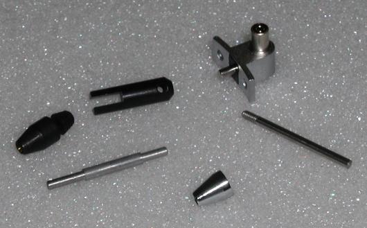
We need to talk about these parts, and that's a lot easier if they have names, so let's make some up. I was considering calling them things like “reciprocating dingle arm”, “squidget”, and “veeblefeetzer”, but I settled on the more mundane terms given below.
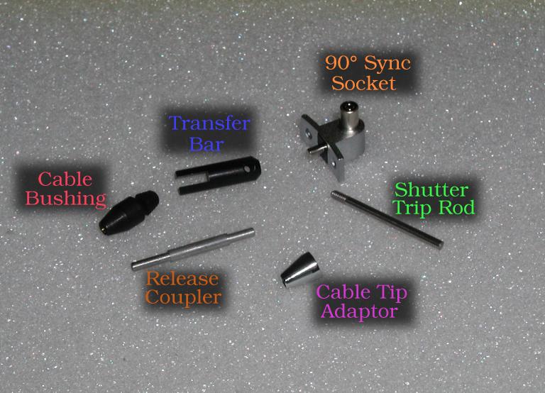
I'll use the colour of the legends in the above picture each time I refer to a component in the text below.
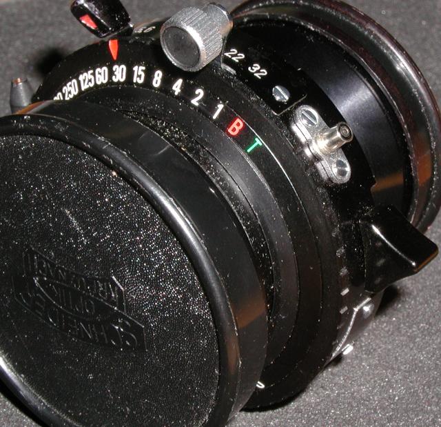
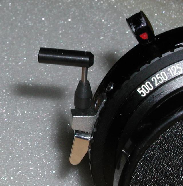
The first problem involved in mounting a lens in a Technika recessed lensboard may escape your attention until the first time you need to use flash, whereupon your discover that there is absolutely no way you can fit your PC flash plug into the socket on the shutter now that it's immured in the recess of the lensboard. Fortunately, the 90° Sync Socket provides the solution. This is installed before mounting the lens in the lensboard. Here's the original flash sync socket installed on a Schneider Super Angulon 47.
Working on a surface which doesn't encourage tiny parts to roll off and disappear into the fifth dimension (you know, where cat hair comes back from, ten years after Meepo has gone on to his reward), unscrew the two screws retaining the sync socket and remove it. It's best to use jewelers' screwdrivers with fine blades and pivoting ends, as they're less likely to slip and score the shutter, creating a cosmetic defect which will reduce the lens' value should you later wish to resell it.
Now install the 90° Sync Socket in place of the original socket and secure it with the screws used by the original socket. These screws are tiny and extremely difficult to pick up by hand; it's best to use fine-tipped tweezers which can grasp them and insert them in the holes as you move the angled sync socket into position.
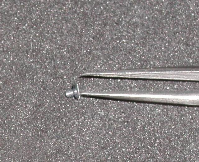
After installing the 90° Sync Socket it's time to turn to the Cable Bushing. Start the bushing into the screws of the cable socket by hand, then secure it firmly (but not so aggressively you strip the threads) using the screwdriver slot cut at the top of the bushing.
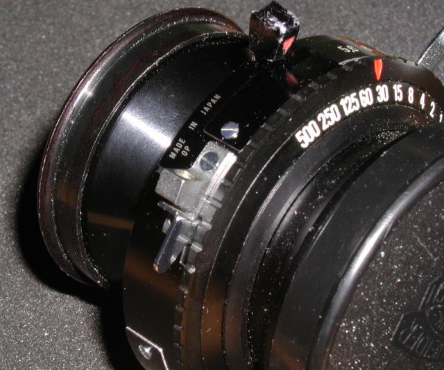
Here's how your lens should look after you've installed the 90° Sync Socket. Note that a lens with this flash socket remains perfectly usable on a flat lensboard. You should test the shutter to make sure the flash still works; you can do this before mounting it—simply attach your flash, cock the shutter, and press the release, verifying that the flash fired. To be extra sure, remove the lens caps and verify that the flash-illuminated scene is visible through the shutter over the rated sync speeds, although if you have a problem with this, the 90° Sync Socket is almost certainly not to blame.
Note the Cable Bushing installed in the cable release socket at the left.
In order to mount the lens in the lensboard, it must first be disassembled. Both the front and back lenscaps should remain in place throughout the entire mounting process. Grasp the front and rear components of the lens by the lenscaps (or, if they slip, by the lens body below them) and unscrew the rear lens component from the front component and shutter. Set the rear component aside. If you're working in a dusty environment or intend to leave the rear component unmounted for a lengthy period, cover it to protect the exposed rear lens from dust.
Next, unscrew the retaining ring from the front component of the lens. If the retaining ring is tightly fastened, you may need to initially loosen it with a spanner wrench adjusted to engage the slots at the edge. You should then be able to unscrew the retainer ring with your fingers.
When buying a used lens, make sure the retainer ring is present; if you're buying sight unseen, on an auction Web site, for example, don't hesitate to contact the seller if you're unsure whether the retainer ring is included. You can order replacement retainer rings, but it's best to avoid the nasty surprise, delay, and additional expense when you discover the ring is missing only when you're about to mount the lens.
Locate the black slotted Transfer Bar and the threaded Shutter Trip Rod bar. Note that the hole in the Transfer Bar is threaded.
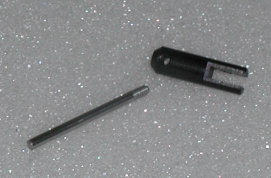
Screw the Shutter Trip Rod into the threaded hole in the Transfer Bar and tighten “finger tight”.
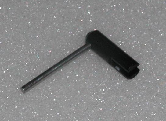
Now place the unthreaded end of the assembly into the hole in the Cable Bushing so that the end of the Shutter Trip Rod rests upon the shutter release lever. Align the Transfer Bar so that it points more or less away from the lens.
Take the front element of the lens and insert it in the hole in the lensboard with the front element within the recessed cavity. Position the front element so the aperture setting and shutter cocking levers are toward the top (the edge without the notch). Secure the front element by screwing the retainer ring onto the threads protruding through the rear of the lensboard.
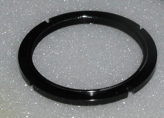
Note that the retainer ring has a raised ridge on one side. The ridge should face toward the front element of the lens. When you tighten the retainer ring, the ridge will extend into the hole in the lensboard and guarantee the lens is centred. The retainer ring and front element have very fine threads; it is easy to “cross-thread” and damage them. If you encounter resistance when you first start to tighten the retainer ring, back it off, realign it and try again.
As you continue to tighten the retaining ring, eventually you'll feel resistance as it reaches the lensboard. In most cases this will be due to the ridge binding on the edge of the lens cutout. Loosen the ring a fraction of a turn, then shift the lens until the ridge drops into the lens cutout, then continue to tighten. Once the retaining ring is “finger tight”, back it off a little so you can rotate the front element for the subsequent alignment steps.
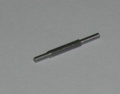
Locate the Release Coupler—that's the cylindrical rod with a thick section in the middle and two narrow sections at the ends. Note that one of the narrow sections is longer than the other.
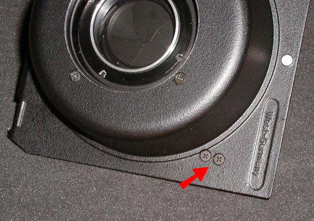
Before installing the Release Coupler, turn the lensboard over so the back is toward you and loosen the two screws that secure the cable release connection (the gizmo attached to the lensboard with the red button on the front). Don't remove the screws—just loosen them sufficiently to permit shifting the cable release coupler.
Turn the lensboard so the front element is toward you and insert the Release Coupler into the cable release connection with the long narrow end protruding. You may have to rotate the lens counterclockwise to gain sufficient clearance to insert the Release Coupler. If the lens binds, loosen the retainer ring until it turns freely.
Now comes the tricky part. Rotate the lens until the Release Coupler fits into the slot of the Transfer Bar without binding. When things are properly aligned, the Transfer Bar should be almost touching the pointed end of the cable release connection and when you press the transfer bar downward, the Release Coupler should slide freely from the cable release connection and the Shutter Trip Rod should actuate the shutter release. Try cocking the shutter and verify that pressing the Transfer Bar fires it. Also be sure that when you release the Transfer Bar, the spring in the shutter release pushes the assembly back without binding.
If you have trouble with this, it's just a matter of looking at the mechanism close up and fiddling with alignment until it works smoothly. The two degrees of freedom are the alignment of the cable release connection and the orientation of the lens in the mounting hole. Once you're happy with the alignment, tighten the screws on the back of the lensboard to lock the cable release connection in place and finger-tighten the retainer ring to secure the front element of the lens.
With the front element aligned with the cable release contraption, we now wish to secure it in that position. Normally, you need only tighten the retainer ring with a spanner wrench, but many spanner wrenches won't fit into the close confines of the recessed lensboard's back element well. If you encounter this problem, you can tighten the retainer ring by carefully twisting it with two jewelers' screwdrivers.
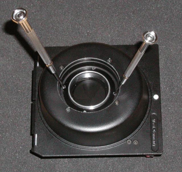
If you use this technique, it's best to ask a friend to hold the front element and lensboard so your tightening the retainer ring doesn't rotate the front element, wrecking the cable release alignment. After securing the front element to the lensboard, it's a good idea to re-test the shutter release via the Transfer Bar to be sure you didn't accidentally twist the lens and cause it to bind.
With the front element mounted on the lensboard, the rear element may now be re-installed. If dust is visible on the rear element lens, you may wish to use a “canned air” spray to disperse it. The same goes for the shutter, but use extreme caution—high pressure air can lift shutter blades and damage them. It's best to use a mild stream of air from a distance rather than blasting away at close range.
As with the retainer ring, be careful not to cross-thread the rear element when installing it. If you encounter resistance, back it out, turn it, and retry the installation. The back element need only be tightened “finger tight”.
Here's the lensboard after the back element has been installed. At this point we're done with the lens and lensboard and can turn to the cable release.
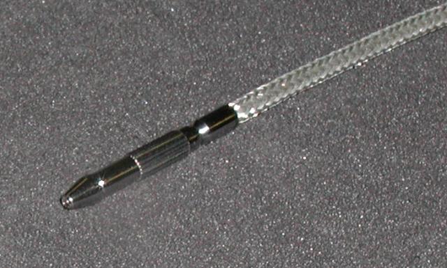
The cable release connection on the recessed lensboard doesn't accept a standard screw-in cable release. Instead it's designed for a “quick release” cable, but fortunately, the included Cable Tip Adaptor converts a conventional cable release to this interface.
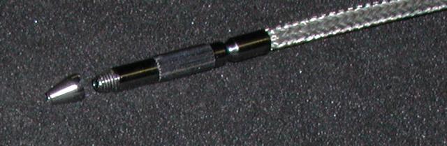
Take a standard threaded cable release and fasten the Cable Tip Adaptor to the end. Once again, “finger tight” is adequate—leave the Vise-Grip in the tool box.
You should now be able to plug the cable release into the cable release connection and test whether it correctly operates the shutter release. Try cocking the shutter at various speeds and verifying that the cable release actuates the shutter and that the shutter release's return spring returns the cable to the starting point when you release it. If something binds, you'll need to remove the rear element, loosen the retainer ring and cable release connection attachment screws, and twiddle alignment until it works properly. Hey…I didn't design this sucker, I'm just trying to explain how to make it work!
When you plug your adapted cable release into the cable release connection, rotate it one revolution clockwise between your fingers. This ensures the cable tip engages the latch in the connection. Here's the cable release seated in the cable release connection.
Make sure everything works: try several exposures with the lens and cable release by themselves, including “B” and “T” shutter settings. As long as the cable release doesn't pop out of the socket and the cable release plunger returns after you release it, all is well.
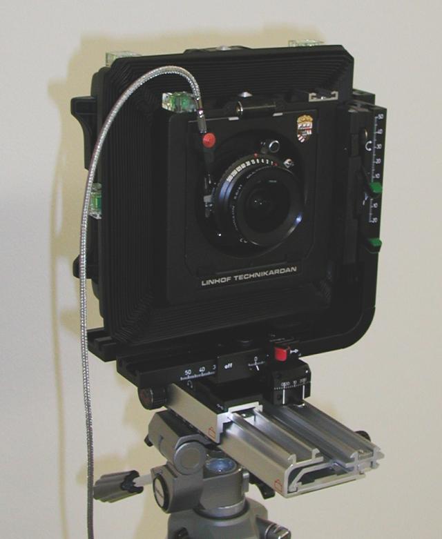
Here's the Super Angulon 47mm mounted on a Technika recessed lensboard installed on my Linhof Technikardan 4×5" camera. Note how the bellows are squashed to bring the lens into focus at infinity. Large format purists may wonder why I'd bother mounting a lens that doesn't even cover 4×5. Well, the Super Angulon 47mm covers the 6×12cm panoramic roll film format, and it's a marvelously compact and inexpensive lens for shooting landscapes and panoramas in the field. The Super Angulon XL 47mm covers 4×5" with minimal movements (most of which require a bag bellows); it's a great lens, albeit larger, heavier, and more expensive. The mounting procedure for the XL is precisely the same.
The cable release connection and 90° Sync Socket handle the external interface issues, but the recessed lensboard poses additional human interface problems. The shutter speed dial is easy to set, but the aperture setting and press shutter opening controls are well buried in the recessed lens bay and not easily accessible.
If you, as I, find Robert Wheeler's Vade Mecum an essential tool for your large format photography, you'll always have a Palm stylus at hand when exposing negatives. A Palm stylus is the perfect tool for adjusting the aperture and opening and closing the shutter for composition.
This document is in the public domain. Permission to use, copy, modify, and distribute this document for any purpose and without fee is hereby granted, without any conditions or restrictions. This document is provided “as is” without express or implied warranty.
|
|